Following his arrival in London in late 1884, and understanding that Russian warships armed with highly effective Krupp guns were likely to be the principal foe of the Australian colonies, Major General Scratchley sought to gain approval from the War Office to purchase of a range of Breech-Loading guns for Victoria. Scratchley’s armament choices were continued when the role of Military Advisor to the Australian Colonies was transferred to Major-General Edward Harding Stewart R.E. in 1885. However, the War Office Ordnance department made it clear colonial requirements would not be supplied until Royal Navy requisitions were fulfilled, so Victoria directly placed gun orders with Armstrong & Co. The decision meant the six barbette emplacements still under construction at Fort Nepean were already obsolete.
Two years earlier Victoria and N.S.W. had financed trials of 80-pdr ‘chilled’ Palliser shot at Shoeburyness,(i) where, fired using 20-lb of pebble powder at a range of 70 yards and velocity of 1400-ft/second, the ribbed and jacketed chilled Palliser shot had passed clean through a 6-inch iron plate. This degree of success was quite unexpected and appeared the 80-pdr R.M.L.’s remained a competitive match to Krupp steel guns and shells used in the Russian Navy. Arming the Port Phillip ‘Jervois’ fortifications fell into disarray over deciding upon using Palliser shells and retaining the 80-pdr’s in open batteries; acquiring Armstrong ‘disappearing’ carriages and shields; replacing the R.M.L. guns with B.L. guns of similar calibre. While the second choice was proceeded with Victoria eventually purchased twelve 5-inch B.L. guns to be mounted on the Armstrong hydro-pneumatic carriages under order for batteries at Point Nepean (5), Queenscliff (4), and Swan Island (3). (ii)
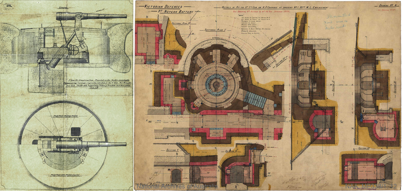
Left: 5-inch HP gun Plan & elevation – drawing attached to contract 2208/1885 forwarded by Major General Harding Steward. N.A.A. B3756/0; Item 1886/910; barcode 5797776 Right: N.A.A. MP338/1 15; barcode 1842332. Eleven of the twelve 80-pdr H.P. mountings ordered in 1885 were converted to carry 5-inch R.B.L. guns before deliver to Victoria. This drawing for Nepean emplacement 1 was one of four guns of 5-inch calibre proposed to be located at Fort Nepean to replace the four 80-pdr RML’s.
The problem still consuming coast-fortification engineers (of all nations) was how to counter the penetrative power of increasingly sophisticated warship ordnance. While forts in Gibraltar, Malta and Bermuda received 12.5 inch R.M.L. guns mounted in massive concrete barbette emplacements in 1878, by July 1879 the British Committee of Ordnance (appointed a month earlier to examine the issue of Breech loading v’s Muzzle loading) was recommending the R.G.F. manufacture 12-inch B.L. guns of 43-tons for the Spithead forts and 10.4-inch 21-ton B.L. guns for general coast defence. The Admiralty had then requested a 9.2-inch B.L. of 18-tons, which became the primary coast artillery gun – as a counter to Krupp’s 24-cm. gun. When the 8-inch Mk1 and Mk2 R.B.L. guns developed by the R.G.F. did not meet expectations the Admiralty abandoned 8-inch ordnance.(iii) However, in 1884 at Imperial request, one of the Port Phillip Armstrong Elswick Co. (EOC) 6-inch guns was sent with its H.P. carriage to be tested at the Shoeburyness range, and was reported to be a complete success.
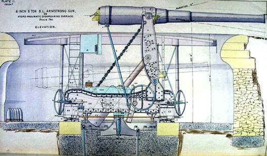
6-inch B.L. 5-ton Armstrong gun on Hydro pneumatic ‘Disappearing’ Carriage. – Guns 3 &5 were positioned at Fort Nepean in 1886-7. Image – Collection: N.A.A. A1194 17.10/5916 page 31
Although far more expensive to manufacture, it was postulated that large calibre R.B.L. ordnance mounted in protected batteries (20-25 calibres in length and fired with prismatic ‘Cocoa’ powder slow burn charges rather than black powder) would safely allow a substantial reduction in the number of R.M.L. guns required in a coastal battery. By 1884 three British manufacturers had successfully applied the Hydro-Pneumatic principal to B.L. guns of 6-inch, 8-inch, 9.2-inch, and 10-inch calibres. They were Moncrieff’s Easton and Anderson Company, (E & A) Armstrong’s Elswick Ordnance company (E.O.C.) and the Woolwich Royal Carriage Department (R.C.D.). Each had put forward designs that competitively tested before the Director of Artillery was willing to accept them for service use. Tests for the 10-inch B.L. took place at Landguard (E & A mounting) and at Shoeburyness (E.O.C. and R.C.D.). The 9.2-inch B.L. guns were tested at Grain. Following a recommendation from Scratchley, Armstrong’s successfully sold three 8-inch guns with H.P. mountings to Victoria; one of which was temporarily retained in the U.K. for Imperial evaluation at Shoeburyness. In 1886 The War Office published a – Treatise on the Manufacture of Guns & Text-book of Service Ordnance,’ which offered 500 pages of detailed information on British gun metallurgy, barrel structure, aiming devices, plus extensive calculations covering muzzle velocity, range and the rapidly evolving science of gunnery.(iv)
The breadth of responsibility for Victoria’s major decision changes in defence planning, fortification structures, and ordnance purchase, following Major-General Sir Peter Scratchley relinquishing the role of ‘Military Advisor to the Australian Colonies’ in 1885 is opaque. While Major-General Edward Harding Steward R.E. (1885-1891) was clearly acknowledge by Defence Minister Sir James Lorimer when returning from the London Colonial Conference – 1887,
“I am certain we are working on the right lines, that everything is well designed, and that our armaments are of the most modern description. In fact they are in advance of anything I have seen in England, thanks to the counsel and assistance of General Harding Stewart, military advisor for the colonies.” (v)
Two years earlier Victoria’s Agent General had telegrammed from London that he had received a memorandum from a defence conference embracing Harding Steward, Sir William Armstrong, Sir Andrew Clarke, Captain Jackson R.N., and Captain G. Clarke,(vi) which had recommended placing an advanced line of electrical mines between the principal Heads forts – Fort Queenscliff and Fort Nepean, or, Queenscliff and Observatory Point, with secondary lines at Swan Island and South Channel annulus. The advanced line would require an increase in the guns near Queenscliff, and guns at Observatory Point.(vii)
Alternately, Confidential Report – No.15r,(viii) sent from the Colonial Defence Committee to Lorimer as Defence Minister in 1888, acknowledged that the colony’s own ‘Defence Council’ had drawn up a scheme for the Defence of Victoria in 1886, using the memorandums on Port Phillip defence provided by Lieut. General Sir A. Clarke, Rear Admiral Sir G. Tryon, Lieut. General Sir W. Jervois and Major General Schaw.
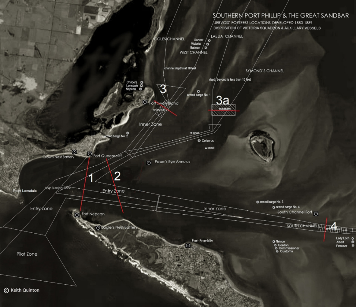
Port Phillip Heads Defence Zones – circa 1885-1887: Zone 1: Lonsdale/Queenscliff/Nepean – Experimental line of submarine mines (1887). 2. Proposed Queenscliff/Observatory Point – Line of submarine mines (1887). Zone 2: Queenscliff/Observatory Point: Zone 3: Swan Island (1885). Zone 4: South Channel (1885) Map: Author
Lorimer had delivered three defence memorandum on returning from the 1887 Colonial Conference. Each proposed different gun distributions within two agreed defence zones – No.1:- Queenscliff, Crow’s Nest, Lonsdale, Nepean, East Nepean, (19 B.L. guns & 1 RML) and No.2:- South Channel, Franklin, and Swan Island (12 B.L. guns & 2 RML’s).(ix) The ‘outer’ zone was premised upon establishing a line of submarine mines across the deep ‘rocky channel’ between Queenscliff and Nepean, with the retention of the secondary ‘inner’ lines of mines in West Channel and South Channel. Construction of a Brennan Torpedo station at the outer zone was thought desirable – if made available by the War Office.
However, the decision to create a forward defence at Pope’s Eye shoal to protect a deep water line of ‘ … 500-lb electrically discharged ground mines running somewhere between Queenscliff and Point Nepean’ was proposed by Major General Schaw who departed New Zealand in March 1887 to advise on the Heads defences at Port Phillip. His report led to placement of the majority of new B.L. guns near Port Phillip Heads and renewed interest in constructing a fortification on Pope’s Eye Shoal. Most of the acquired B.L. guns and H.P. carriages were in transit from the U.K. While Schaw’s advice received considerable support in the colonial press, further government decisions on ordnance requirements and gun placement remained fluid.
Four of the six 1885 Point Nepean emplacement structures were re-mounted with an Armstrong R.M.L. 80-pdr during 1886. However, by July 1887, John Blackbourn had completed drawings for emplacements No.1 and No.2, to be converted into two 5-inch BL H.P. positions, linked by underground passages, and new protective revetment earthworks that included an improved infantry parapet and banquette. Around September 1887 the 80-pdrs were dismounted to enable contractors, W. G. Priddle and F. T. Rogers to commence construction. The Colonial Defence Committee was informed the new works would be completed by July 1888.(x)
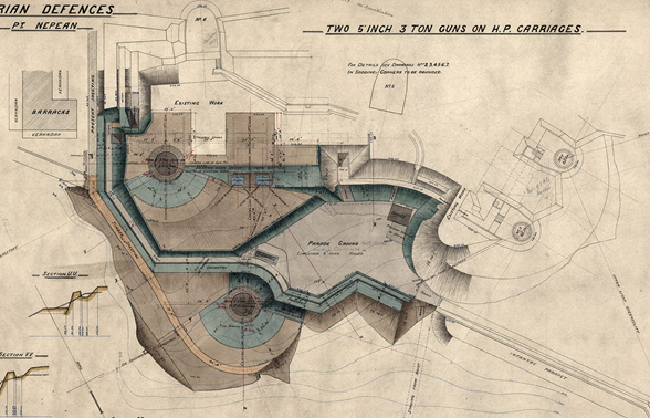
Above: This September 1887 contract drawing indicates the restructure of emplacement No.1 with a 5-inch HP gun and the conversion of emplacement No.2 to a dual Watkins range finder position. The second 5-inch HP emplacement is located forward of the new infantry parapet and banquette enclosed parade ground. The selected gun calibre had been increased to 6-inch BL in November 1887. NAA Drawing barcode 1842699
The Nepean fortification layout was most likely confirmed by the five Imperial Officers who had arrived to form Victoria’s Military Staff in 1885; with their plans confirmed in the Victorian Council of Defence by early 1887.(xi) Assistant Adjutant-General of Artillery Colonel A. G. Walker was acknowledged as the most significant contributor following the conclusion of five years’ service in 1889.(xii) After the departure of Major-General Scratchley contract drawings were produced by a small three man Defence section in the Victorian Public Works Department; a section headed by John Blackbourn – an internationally experienced civil engineer who had been made Scratchley’s assistant in 1882. Blackbourn continued to play a significant role in constructing the fortifications at Port Phillip, and at Albany in Western Australia, until retirement in 1904. The 1909 War Office ‘Blast Safety Chart’ (below) indicates safe distances for British gun calibres, and provides the technical reasoning behind the markedly increased spacing between Fort Nepean’s B.L. gun emplacements, particularly as the level area on Point Nepean’s headland knoll covered less than 1,000 sq. yards and was surround by highly unstable steep sand escarpments.
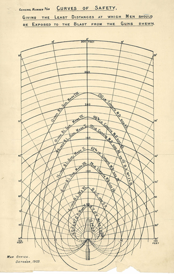
Above: Blast Chart – Improved British ‘cocoa’ brown prismatic gunpowder. C. 1902 Gas checks on projectiles and elongated gun barrels dramatically increased gun range by ‘graduating’ powder burn. When a shell left the barrel of 1880- 90’s R.B.L. ordnance increased spacing safeguarded batteries from severe blast percussion. Image: Author’s collection
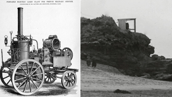
In April-May 1885, experiment with Sautter-Lemonnier electrical machines and Siemens carbon-arc electric searchlights had been successfully conducted at Fort Queenscliff and Fort Nepean.(xiii) In May 1885 the Age newspaper reported the equipment had been purchased two years earlier and stored by the Torpedo Corps at their Swan Island depot. Accompanying General Owen, Colonel Walker, Major Rhodes, Mr Steel – Inspector General of Public Works, and Mr Blackbourn, on their inspection of the Heads works, he had observed ‘…. at Point Nepean battery the 9-inch muzzle loading Armstrong gun is in position and ready for action, the magazine being completed, and the parapet earthworks well forward. The schevonier (banquette) at the side of the 80-pounder battery is also well advanced, and the electric shed and engine completed ready for use.’(xiv)
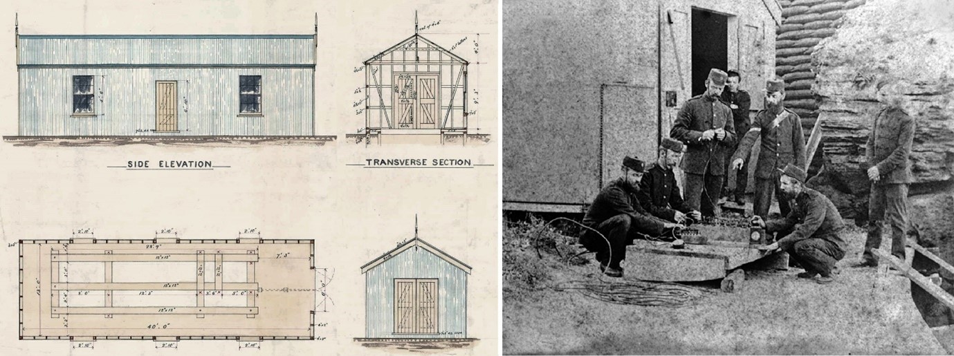
Above left: In 1885 Electrical Lighting sheds were constructed at Queenscliff, Swan Island, and Point Nepean, to house Victoria’s four Sautter-Lemonier electrical machines to power searchlights . NAA Drawing – Barcode. 30477373
Above Right: Victorian Submarine Miners in front of the Point Nepean electrical shed when Major Rhodes and the Submarine Mining Engineers experimentally tested ground mines positioned between Queenscliff and Point Nepean during Easter 1887. The Nepean corrugated iron shed was completed in July 1885 and a red-gum lined electric light gallery was cut through the sandbag revetment to the outer rock shelf in November 1887. Image: Photo Collection Fort Queenscliff Museum
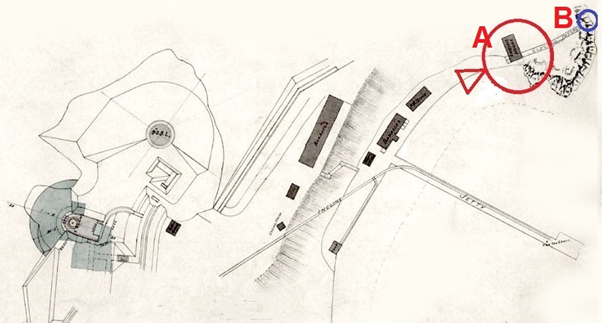
Below: Work on a permanent concrete covered ‘bombproof’ engine house (A) was commenced in July 1888 to connect with a timber searchlight hut (B) NAA MP338/1.47 Barcode 1843065 (section)
In 1886 ‘The Argus’ newspaper reported Captain Thomas of the Victorian Naval Reserve and commander of the monitor HMVS Cerberus had stated; ‘From experience gained whilst attacking the forts at night, I am of opinion that on a dark night the forts would be powerless to stop an enemy’s ship going at a high rate of speed, unless supplied with electric lights which, placed at Queenscliff and Nepean, would command the ¡entrance – through the Heads.’ So palpable and serious a deficiency could not for long be left unremedied, and the Defence department have since had erected the apparatus necessary to throw a broad beam of light from fort to fort between the Point and Queenscliff. The ‘Saulter Lemonier’ light at the lower lighthouse station on the hill is said to be of 50,000 candle power, and that at Point Nepean of 25,000 candle power. Both these are fixed lights, but on the ramparts of the Queenscliff Fort, in a spot best fitted for wide observation, there is a moveable Siemens light, of similar illuminating power to the one at Point Nepean used for sweeping the surface of the waters round about the cliff, to provide against a sudden attack from any craft that might be lurking about in the vicinity.’(XV)
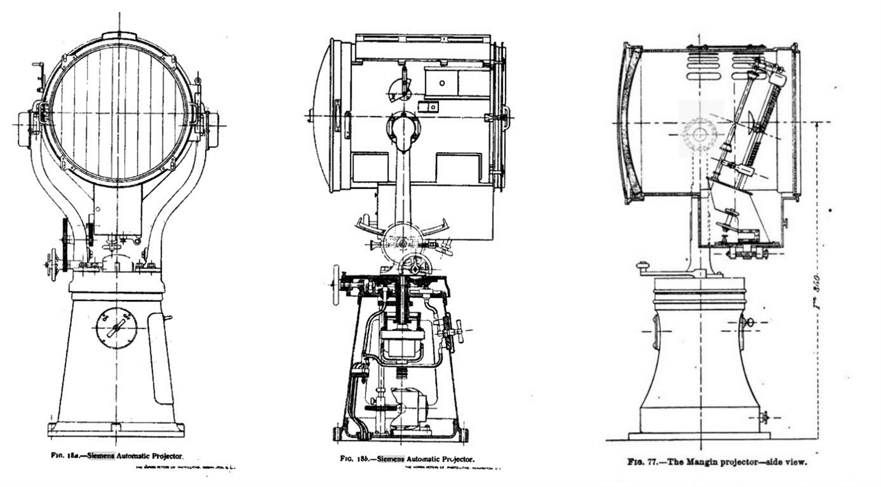
Above: Siemens lamp (left & centre) and Mangin lamp (right) Carbon-arc electric light projectors (used by Sautter-Lemonier) – circa 1885-98. 1897-8 Secret memorandum No. 168M C.O. No. 16707 S ‘Electric Lights at Port Phillip’ by the Colonial Defence Committee listed six steam engines and one Priestman oil engine (1892) held at Swan Island – two for Nepean, two for Queenscliff, two for south channel, and one for instructional purposes at Melbourne. (Williamstown Torpedo Mine Depot) There were eight 3-ft Mangin type projectors. It is likely the vertical tube boilers and engines were British manufactured by the engineering firm Peter Brotherhood. These were connected to twin Gramme type dynamos (Société des Machines Magnéto-Électriques Gramme).(xvi)
While the electric light on Fort Queenscliff eastern boundary was probably a mobile Siemens searchlight, other Victorian searchlights, including the Nepean light, were Mangin type projectors – as displayed at the Military lighting section of the ‘1882 Paris International Exposition of Electricity’ by French manufacturer Sautter-Lemonier. The company appear to have combined a vertical multi-tube boiler and three cylinder engine (constructed in the UK by engineer Peter Brotherhood) with Gramme type dynamos and Mangin lamp projectors. (At this time Zénobe Mangin held the manufacturing license for Gramme magneto electric machines.) Hundreds of ‘military’ electric light units were being purchased for warships and coast defence purposes by Britain and other European powers and it is likely the Victorian units were supplied via the British Board of Ordnance, rather than the manufacturer.
Above Left: Sautter-Lemonier portable Military Electric Light exhibited at the 1882 Paris Exposition of Electrical Machinery. The vertical Brotherhood multitube boiler and three cylinder engine are mounted on the left and linked with two Gramme dynamos, a power cable reel, and portable searchlight. Image: Graces Guide. The Engineer 1885/11/27
Above Right: Searchlight at Point Lonsdale Lighthouse precinct. c. 1904. It is likely the two searchlight positioned at Fort Nepean, circa 1885-1900, were located in similar timber shelters. Removable wooden shutters would have enclosed the projector when not in use. Photo (section): Collection State Library of Victoria.
Port Phillip’s defence plan for fortifications and harbour defence vessels was inextricably linked to lines of submarine mines blocking the shipping channels. Electrically discharged mines relied upon highly accurate positioning and a corresponding accuracy in plotting the movement of enemy vessels. Two ‘Horizontal Submarine Mine Position Finder’(xvii) devices invented by Captain Henry Watkin R.A. and introduced to British service in 1881 were purchased for Victoria in 1885. One was positioned within Fort Queenscliff, while the second was destined for the South Channel Fort defences – still under construction. By this time Watkin had also perfected his artillery Depression Range Finder for B.L. guns and each of the heavy B.L. guns installed at Fort Nepean in 1887-1889 were linked with individual ‘D.R.F.’s.(xviii)
Successive delays in ordnance supply during 1887 were largely due to Armstrong and Co. being overwhelmed by the multiplicity of international requests for B.L. ordnance. ‘War Material Ordered’ from Armstrong’s for the financial year 1886-1887 listed – one 10-inch gun; four 9.2-inch guns; two 8-inch guns; two 6-inch/5-ton guns; fifteen 5-inch guns (4 shipped); and twelve 6-pounder Nordenfelt quick-firers on balanced pillars. The expectation was that all but one 9.2-inch and two 6-inch guns could be shipped within the year.(xix) The planners linked the existing underground powder and shell magazines to the H.P. gun pits with underground tunnels. The batteries could now fight at ranges beyond 4,000 with substantial accuracy and out to 7,000 – 10,000 yards at maximum range; while the simple tangent sights previously attached to M.L. gun barrels for predictive ‘line-of-sight’ fire had not provide range accuracy beyond 2,500 – 3,000 yards. The ability of the forward defence to resist the entrance of enemy warships of the ‘protected’ cruiser class had dramatically improved.
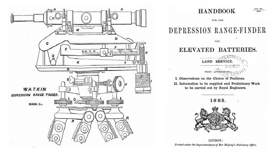
Images: 1885 Handbook for Watkin Depression Rangefinder for Elevated Batteries.(xx) – Collection: S.L.V.
No.1 emplacement was converted to a 6-inch H.P. emplacement and the second 6-inch HP ‘forward’ emplacement was constructed just beyond the infantry parapet around 80-ft to the North. It was connected by a tunnel to No.1 magazine and the central gallery system. Twin concrete D.R.F. observation positions were located directly over the foundations of No.2 80-pdr emplacement to control both guns.
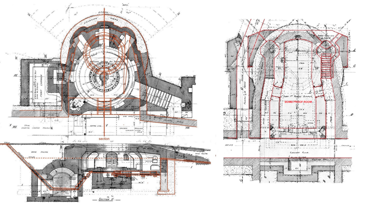
Above Left: Fort Nepean 6-inch H.P. Emplacement c. 1887 (previously 1885 80-pdr Gun No.1). (Red lines indicate the 80-pdr emplacement.) Above Right: Fort Nepean Twin Rangefinder Emplacement & bombproof shelter (Red lines indicate the 1887 D.R.F. alterations positioned over the 80-pdr gun No.2. emplacement) Image: The Author.
Various sectional drawings of the main gallery passage, side passages, magazines, timber revetments, and the two 6-inch H.P. emplacements indicate why some contemporary journalists and later historians have described the 1887 Nepean battery works as ‘… resembling a miniature Gibraltar’. In fact Gibraltar rising more than 1000 feet above the sea with 1½ miles of natural caves and defence tunnels, 50 barbette batteries, and over 200 guns (mostly aging muzzle loaders) in no way resembled the sophisticated defence system that was evolving at Port Phillip Heads.
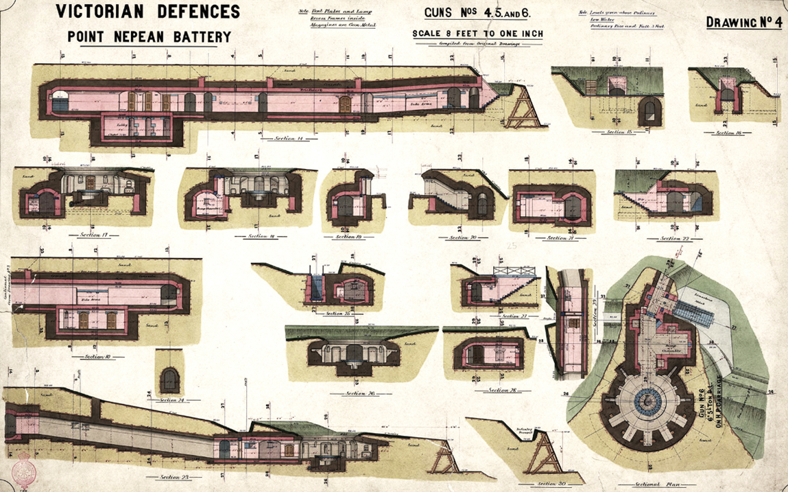
Above: Victorian Defences. Point Nepean Battery. Guns No’s 4, 5 and 6. NAA MP338/1 5 barcode 1842252
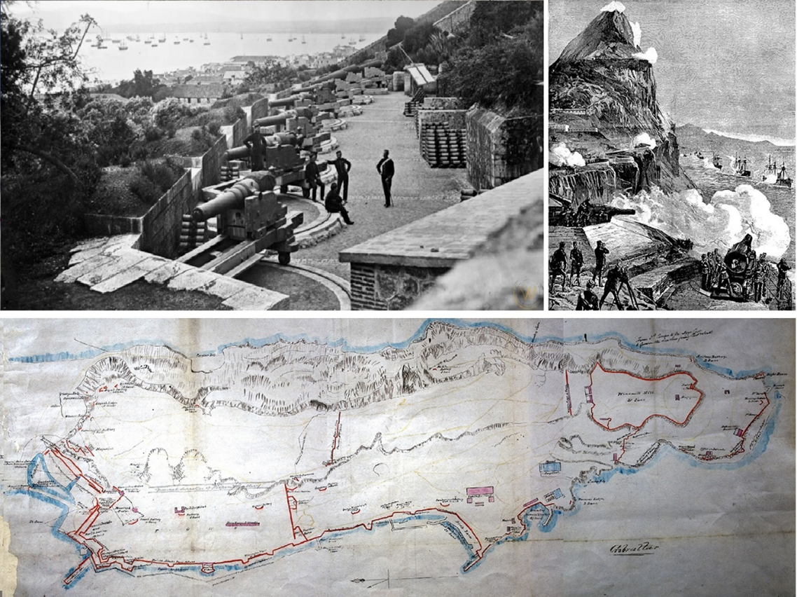
Images clockwise from top left: 1. Gardiner’s Battery, Gibraltar, c. 1880. Five 7-inch rifled screw-breech guns and two 68-pdr ML guns. Image. Wikipedia
2. Europa Point Batteries engaging the Channel Fleet. Image: The Illustrated London News; March 13, 1889.
3. Gibraltar: Map shows the spread of naval and military establishments, bastions, batteries, magazines and other defence works, c. 1859. U.K. National Archives MPH 1/23. Wikipedia
(i) Each colony paid £50 towards the tests conducted by the Ordnance Committee over 2 years to develop chill hardened 80-pdr projectiles. In 1884 N.S.W. ordered 1200 80-pdr ‘Palliser’ armour-piercing shells for their converted 80-pdr guns.
https://trove.nla.gov.au/newspaper/article/13540933?searchTerm=palliser%20shells.%20victoria&searchLimits=
(ii) The overhead shield was eliminated to reduce the combined weight of the gun, HP carriage, and gun platform, upon the racers.
(iii) Hogg, Ian V. Coast Defences of England & Wales 1856-1956. David & Charles (Holdings) Ltd; 1974. pp 71-73
The RGF 9.2 inch BL gun mount encountered design defects that delayed coastal defence distribution until 1889-1890
(iv) Treatise on the Manufacture of Guns & Text-book of Service Ordnance. HM Stationary Office. 1886 https://babel.hathitrust.org/cgi/pt?id=mdp.39015027213027&view=1up&seq=1
(v) Age. 9 September 1887. Return of the Minister of Defence. Page 5
(vi) Sir A. Clarke,(Chairman) Captain Jackson R.N. (Naval advisor) and Capt. G. Clarke R.A. (Secretary) were key members of the Colonial Defence Committee established in 1885
(vii) NAA Doc. 85/3141 & doc. Ref. NAA 85/3435 – dated 3/10/1885 – Secretary of Defence to Secretary of the Premier.
(viii) NAA: CP601/2, VOL1 Victoria Local Scheme of Defence. Report by Sir James Lorimer on Proposed gun positions 1886
Queenscliff
3 9.2-inch B.L. Guns
3 6 –inch B.L. guns
1 80-pdr RML gun
Crow’s Nest
1 8-inch B.L. gun
2 5-inch B.L. guns
Lonsdale
1 10-inch B.L. gun
2 5-inch B.L. guns
Nepean
2 9.2-inch B.L. guns
3 6-inch B.L. guns
East Nepean
1 9.2-inch B.L. gun
1 5-inch B.L. gun
(x) ibid
(xi) Four of the five 1887 Imperial Staff officers had been appointed in 1882, one in 1884. In Victoria the Imperial request for a Standing Defence Committee to report to the UK 1885 Colonial Defence Committee was assumed by the Council of Defence.
(xii) Brisbane Courier. 6 May 1889. The Defences of Melbourne (from the Argus). Page 6
(xiii) Office of Naval Intelligence. General Information Series No. XIX Information from abroad. Notes on Naval Progress July 1900 -Searchlights pp 264-265. Google E-books free.
Age. 4 May 1885 ‘The Defences at the Heads’ page 6 ‘Each one is driven by a vertical engine with inverted cylinder. The boiler is also vertical and multitubular. The dynamo gives a 16,000 power candlelight. The apparatus for concentrating and throwing the rays of light across the water consists of a specially made Siemens lamp and reflector, such as is used on board English men-of-war. It is calculated that the light will brilliantly illuminate in the darkest night an object 4000 yards away.
(xiv) Geelong Advertiser. 3 July 1885. The Defences. Page 3
(xv) The Argus. 4 June 1886 ’Testing of the electric Lights’ Page3
(xvi) U.S. Annual Report to the Secretary of the Navy for the year 1884. Military Electrical lamps.
(xvii) A sophisticated telescope system derived from theodolites, also referred to as a Horizontal Range Finder
(xviii) Captain Henry S.S. Watkin R.A.
Protracted trials of his Depression range Finder were held between 1876 and 1881, when it was put into service under a cloak of secrecy.
(xix) Argus. 27 July 1887. Report of the Defence Department. War Materials received during the financial year. 1886-7. Page 11
(xx) Land Service. H.M. Stationary Office. Handbook for the Depression Range-finder for Elevated Batteries. 1885 State Library of Victoria Online Digital Copy
Click Here for Fort Nepean – Understanding the trace – Part 2: The Point Nepean Batteries 1882-1885
Contact Keith Quinton about this article.